The SEDRIS Data Representation Model
APPENDIX A - Classes
State Related Geometry
|
|---|
Class Name: State Related Geometry
Subclasses
This DRM class is concrete and has no subclasses.
Definition
A mechanism for specifying discrete states from a possibly continuous
state value. Each discrete state corresponds to a branch of the
<State Related Geometry> and is
identified by the <State Data> for
that branch; the state value itself is given by the
state_tag
of <State Related Geometry>.
Primary Page in DRM Diagram:
Secondary Pages in DRM Diagram:
This class appears on only one page of the DRM class diagram.
Example
Consider a <Model> of a building which has four
different geometric representations, representing different damage states.
The <Model> therefore has a
<Geometry Model>, the geometry of which is organized via a
<State Related Geometry> instance with
4 branches, one for each damage state, as shown below.
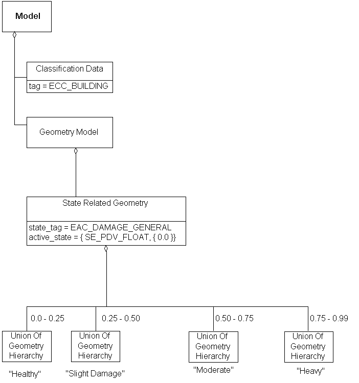
Each branch of the
<State Related Geometry> has a <State Data>
indicating the range of percent damage that the branch represents.
The range values in the diagram therefore specify explicitly
the "bins" in which the states fall.
A slightly different design for example 1, modified to allow
each <Geometry Model Instance> to
specify a percent damage value via a
<State Control Link>.
The
mismatch_behaviour
of the <State Control Link> can be
exploited to 'turn off' the
<Geometry Model Instance> if a damage value is fed in which
does not match one of the damage states. (This is why the
<Model> doesn't require a 'totally destroyed' state for
100% damage.)
If the data provider instead wanted to keep a state transition
from happening until the state value matches a
<State Data>,
SE_STATE_MSM_BHVR_LAST would be specified.
The
mismatch_behaviour
would not be needed if the <Variable> only
took on valid values (0.0, 0.5, 0.75, or 1.0), but this scheme
does not force state values to be discrete.
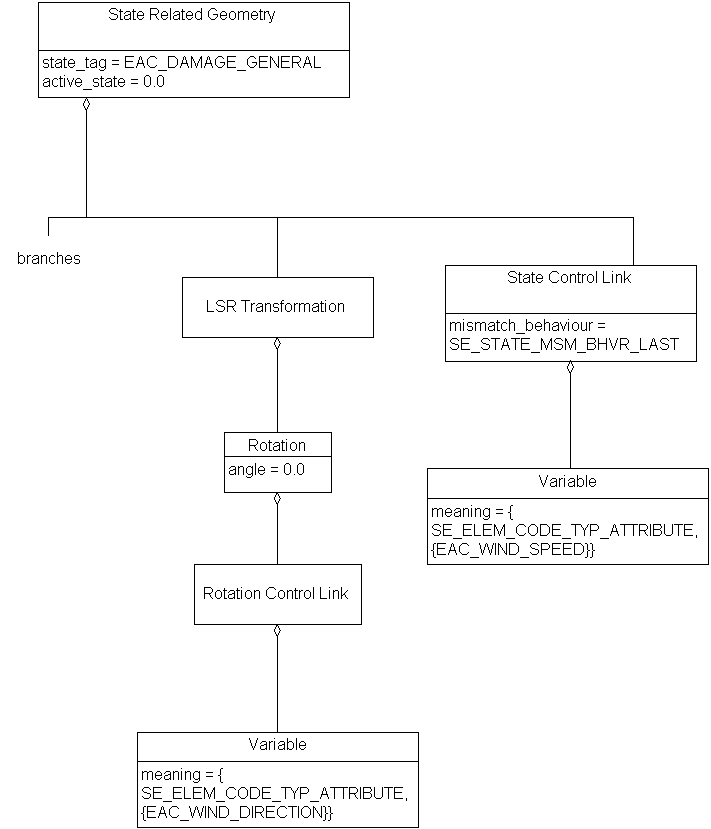
A wind sock model designed to support a landing site has state
behaviour to allow it to respond to wind speed and wind direction.
The wind sock is modeled with 5 states of
EAC_WIND_RESPONSE, where the response to
wind direction is implemented by using a
<Rotation Control Link> tied to an
EAC_WIND_DIRECTION <Variable>.
Identifies one of alternative appearances for some
"state-applicable"
attribute.
For a <State Related Geometry>
representing different states of an aircraft hatch for
EAC_OPENING_COVER_POSITION, one
<State Data> with
EEC_OPNCOVPOS_CLOSED and another with
EEC_OPNCOVPOS_OPEN.
For a <State Related Geometry>
representing different damage states of a building for
EAC_GENERAL_DAMAGE,
<State Data> for [0, 25) % damage, [25, 50) % damage,
[75, 100) % damage, and [100, 100) % damage.
For a <State Related Geometry>
representing different states of a forest for healthy vs. burned,
EAC_GENERAL_DAMAGE could be used.
FAQs
- Is <State Related Geometry>
the only way to represent multi-state objects in SEDRIS?
No. <Control Link> instances can be
used to provide a fine level of control over state by changing fields
instead of representing states as different
<Geometry> instances.
Constraints
Associated by (one-way)(inherited)
Associated with (two-way)(inherited)
Composed of (two-way)(inherited)
Composed of (two-way)
Composed of (two-way metadata)(inherited)
Component of (two-way)(inherited)
Notes
Associated with Notes
 An association between a <Geometry Hierarchy> instance and a
 <Feature> instance indicates that the <Geometry Hierarchy>
 and the <Feature> are alternate representations of the same
 environmental object.
 An association between two <Geometry Hierarchy> instances
 indicates that they are alternate representations of the same
 environmental object.
 An association from a <Hierarchy Summary Item> instance to a
 <Geometry Hierarchy> indicates that the <Hierarchy Summary Item>
 summarizes that <Geometry Hierarchy>.
 An association from a <Reference Surface> instance to a
 <Geometry Hierarchy> indicates that the <Geometry Hierarchy>
 organizes the geometric objects that specify the resolution
 surface of the <Reference Surface>.
Composed of Notes
 In the case where multiple <Collision Volume> components are
 specified for a given <Aggregate Geometry>, the union of the
 volumes thus specified is used in collision detection.
Fields Notes
 If this value is SE_TRUE, each 'descendant' of this aggregation -
 that is, each <Geometry> instance that exists in the component tree
 rooted at the given <Aggregate Geometry> - shall be unique, in the
 sense that it shall appear in only one 'branch' of this aggregation.
 If unique_descendants is SE_FALSE, at least one <Geometry> instance
 appears in more than one 'branch' of the aggregation.
 If this value is SE_TRUE, each 'branch' of this aggregation
 strictly complies with the organizing principle for its
 particular subclass. If this value is SE_FALSE, at least
 one 'branch' does not strictly comply with the given
 organizing principle. See the organizing principle constraint
 for each specific subclass for details.
 This is the state by which the component <Geometry Hierarchy> instances
 are being differentiated, and shall be an EAC which is designated
 as "state applicable".
 This is the default state. If the given <State Related Geometry>
 instance has a <State Control Link>, this field is the target
 of that <State Control Link>.
Prev: State Related Features.
Next: Strobing Light Behaviour.
Up:Index.
|
Last updated: May 15, 2003
|
Copyright © 2003 SEDRIS™
|
|