An instance of this DRM class specifies a unit vector, the
meaning of which is specified by its
vector_type field.
Consider a <Polygon> specified in a 3D LSR
spatial reference frame,
for which a data provider wishes to explicitly provide the
surface normal vector so that consumers do not need to calculate
the surface normal when consuming that particular
<Polygon>.
The data provider specifies this vector information as a
<Reference Vector> component
of the <Polygon> as follows:
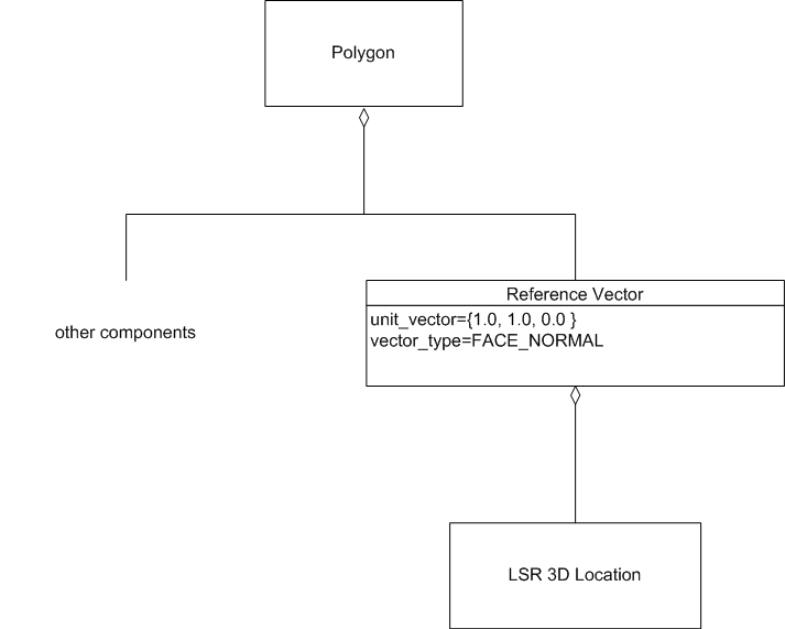
Note that since the <Reference Vector>
is a component of a <Polygon>,
it specifies an <LSR 3D Location>
component in order to comply with
<<Required Reference Vector Location>>.
A <Reference Vector> contained by a
<Polygon>, representing a normal vector that is used
for rendering purposes, i.e. to calculate colour and shading when rendering
the <Polygon>. This
<Reference Vector> would have a
vector_type of
SE_REF_VEC_TYP_RENDERING_NORMAL.
Consider a <Polygon> instance F that
represents an ECC_FENCE, where F is a quadrilateral
as shown below.

F is instanced on some terrain representation, such that the
plane of F is perpendicular to the surrounding terrain.
F has radar cross sections that are dependent on aspect angles
(azimuth and elevation). These aspect angles are defined with
respect to F's normal vector and F's azimuth vector.
Consequently, F has two components.
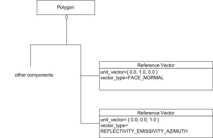
The
SE_REF_VEC_TYP_FACE_NORMAL
<Reference Vector> is the unit vector
that is perpendicular to the plane of F, and which points away from F
on its outside face. The
AZIMUTH
<Reference Vector>
is the unit vector that lies in the plane of F and points straight
up (that is, like F is normal to the plane of the terrain).
A segment of the road has a reflector (actually, a retro-reflector)
on it and is modeled as a <Line>. The
<Line> has a normal vector that is
perpendicular to it and an azimuth reference parallel to it. This is
sufficient to describe radar cross sections of the road as a function of
aspect angles. However, the normal vector for the infrared bands depends
on the orientation of the retro-reflector, not the road. This because
radars see the road but IR (or more obviously, car lights) see the retro-
reflector. In this example, the <Line> instance has
four <Reference Vector> components
(radar-normal, radar-azimuth, ir-normal, and ir-azimuth).
A normal vector used for reflectivity/emissivity calculations. This would
have a vector_type of
SE_REFLECTIVITY_EMISSIVITY_NORMAL.
A vector specifying the direction an
<Infinite Light> illuminates. This would
have a vector_type of
SE_REF_VEC_TYP_LIGHT_DIRECTION.
- Why does
SE_Reference_Vector_Type
have so many entries
that appear to be mathematically similar, such as the
several different varieties of normal?
In the general case, a location on an environmental
object may have distinct vectors for each of these
SE_Reference_Vector_Type
entries, although in specific
instances such vectors may coincide with one another.
For example, consider a large flat window, represented
by a <Polygon> instance. The geometric
normal
(
SE_REF_VEC_TYP_FACE_NORMAL)
in this example coincides with the radar
SE_REF_VEC_TYP_EMISSIVITY_NORMAL
and with the infrared
SE_REF_VEC_TYP_EMISSIVITY_NORMAL.
However, consider a more complex geometric representation -
in this example, a representation of an aircraft. Here the
SE_REF_VEC_TYP_FACE_NORMAL is not
applicable, and the radar and infrared
SE_REF_VEC_TYP_EMISSIVITY_NORMAL
<Reference Vector>
instances do not coincide.
- Why can a <Vertex> have only one
<Reference Vector> component,
when a <Polygon>, <Point>,
or <Line> can have more than one?
A <Vertex>, unlike a
<Primitive Geometry> such as a
<Point>,
does not represent an environmental object, but only part of
an environmental object.
Examples:
To fully describe aspect dependent characteristics as part
of the representation of an environmental object, the
representation requires at least 2
<Reference Vector> components:
NORMAL and AZIMUTH. In addition, a representation of an
environmental object may need to represent a combination
of geometric and/or sensor-related vectors simultaneously.
Since a <Vertex> does not itself
constitute a representation of an environmental object, it
does not require the capability of specifying multiple
<Reference Vector> components.
However, a <Vertex> may need a
SE_REF_VEC_TYP_RENDERING_NORMAL
<Reference Vector>
for use in smooth shading, so a single
<Reference Vector>
component may be needed for a given <Vertex>
instance.
- Why does <Reference Vector>
have an optional component,
and if the <Location> component
is needed to support functionality,
why is it optional?
The SEDRIS API provides the capability of converting
<Reference Vector>
instances between spatial reference frames.
These spatial reference frames include non-vector space
coordinates, such as geodetic. To support those cases, a
<Reference Vector>
requires a <Location> component.
However, in most contexts where a
<Reference Vector> can appear
in a transmittal, the <Reference Vector>
inherits the appropriate <Location>
component from its context, and does not require a
direct <Location> component. See
<<Required Reference Vector Location>> for the cases where an
appropriate <Location> instance
cannot be inherited, so that
the data provider is required to specify such a component
directly for the <Reference Vector>.