The SEDRIS Data Representation Model
APPENDIX A - Classes
Rendering Priority Level
|
|---|
Class Name: Rendering Priority Level
Subclasses
This DRM class is concrete and has no subclasses.
Definition
An instance of this DRM class specifies the method used to describe
the relative priority used to resolve occlusion between 2 or more
overlapping (or potentially overlapping) objects.
Priority is indicated by the group ID
(rendering_group)
and priority index
(
rendering_priority). The
rendering_priority is relative to the
rendering_group,
and is intended to assign priority order (or layer) to coplanar
<Polygon> instances or coplanar
<Feature Representation> instances.
A higher index indicates a higher rendering priority (rendered last).
Objects that do not contain a
<Rendering Priority Level>
are assumed to have a rendering priority value of 0.
Primary Page in DRM Diagram:
Secondary Pages in DRM Diagram:
Example
A particular SEDRIS transmittal may represent a lake as a single
<Polygon> located inside of a much larger
<Polygon> that represents the surrounding
terrain. The larger terrain polygon and the smaller lake polygon
that it contains may be coplanar, so the modeler assigns a
<Rendering Priority Level>
of 1 to the terrain <Polygon> and a
<Rendering Priority Level>
of 2 to the lake <Polygon>, so that the lake
polygon will be rendered on top of the terrain
<Polygon>.
The side of a <Model> can be represented by a
brown <Polygon>, and a window in the side of
a <Model> can be represented by a grey
<Polygon> where the grey
<Polygon>
is coplanar with the brown <Polygon>. The
grey <Polygon> would be given a higher
<Rendering Priority Level> than
the brown <Polygon> so that the window would
be drawn correctly on the side of the <Model>
(where the <Model> could be either a building
or a vehicle).
A Plan View Display (PVD) can display
<Point Feature>,
<Areal Feature>, and
<Linear Feature> instances. Since
<Feature Representation>
are usually considered to be 'flat', many features
are, by definition, coplanar. A
<Rendering Priority Level> can
be used to indicate the relative drawing order (or layer) within a
set of overlapping
<Feature Representations>.
For example,
it is common for a single <Areal Feature>
to cover the entire <Environment Root>
area as a 'default, background'
<Feature Representation>.
This <Areal Feature> could be given
a rendering priority of
SE_RENDER_PRIORITY_BOTTOMMOST so that it would always be drawn
first, and thus would always be in the background.
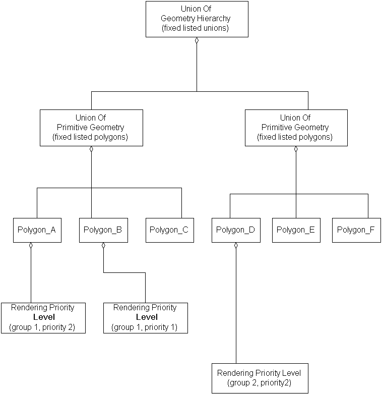
The following instance diagram shows how
<Rendering Priority Level>
can be used to override the layering of a fixed list of objects.
The objects would render in this order: Polygon_C, Polygon_B,
Polygon_A, Polygon_E, Polygon_F, Polygon_D.
FAQs
- Is this the only way to order data for rendering purposes?
No. There are other ways to achieve scope-limited, fixed-ordered
rendering; see ordered <Union Of Geometry>.
- When should a data provider use a
<Rendering Priority Level>?
A <Rendering Priority Level>
should be used to globally resolve rendering priority after
scope limited occlusion is resolved. After all
<Geometry Representation>
is rendered that has a
rendering priority <= 0, rendering successive levels of
<Geometry Representation>
should resolve occlusion.
<Rendering Priority Level>
can be viewed as a sorting bin assignment in some occlusion schemes.
- Are there any 'special' sentinel values for a rendering
priority?
Yes. A rendering priority of
SE_RENDER_PRIORITY_TOPMOST means always render 'on top' (last), and a
priority of
SE_RENDER_PRIORITY_BOTTOMMOST means always render 'on bottom' (first)
Constraints
Component of (two-way)
Inherited Field Elements
This class has no inherited field elements.
Notes
Fields Notes
 The rendering_group field establishes a group to which objects'
 priorities are relative.
 The rendering_priority field indicates priority between coplanar
 objects within the same rendering_group, such that a higher value
 indicates a higher priority.

 For example, a <Polygon> instance with a <Rendering Priority Level>
 component having rendering_group = 1, rendering_priority = 2 will be
 "on top" of a <Polygon> instance with a <Rendering Priority Level>
 component with rendering_group = 1, rendering_priority = 1.
Prev: Relative Time Interval.
Next: Rendering Properties.
Up:Index.
|
Last updated: July 16, 2004
|
Copyright © 2004 SEDRIS™
|
|