The SEDRIS Data Representation Model
APPENDIX A - Classes
Mesh Face Table
|
|---|
Class Name: Mesh Face Table
Subclasses
This DRM class is concrete and has no subclasses.
Definition
An instance of this DRM class specifies a two-dimensional table
that defines the face elements of a
<Finite Element Mesh> instance in
terms of vertex numbers in the ordered <Vertex>
component list of the
<Finite Element Mesh> instance and,
optionally, the topology of the face elements.
The first data element specifies, for cell i, j, the index in the ordered
<Vertex> list of the <Vertex>
representing the jth node of the ith mesh
face. If the ith mesh face contains less than j nodes, so that j is greater
than the number of the last listed node of mesh face i, then the cell data
element contains zero (0). The edges of each mesh face i are implicitly
defined by pairing node j to node j + 1.
For a given mesh face element index i and mesh face node index j, the
(i, j)-th cell gives the vertex number that comprises the j-th node of
the i-th mesh face. The mesh face vertices are listed (j index) in
clockwise order around the outer perimeter of the mesh face, starting
and ending with a first vertex. If inner perimeter rings are present,
the vertex list along the second axis continues with inner perimeter
vertices in counter-clockwise order starting and ending with a first
vertex on each inner ring.
Primary Page in DRM Diagram:
Secondary Pages in DRM Diagram:
This class appears on only one page of the DRM class diagram.
Example
Consider six <Vertex> instances, used to
define a <Mesh Face Table>, where
the mesh would be diagrammed as follows.
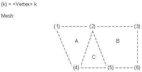
In this example, there are six <Vertex>
instances forming the nodes of the mesh, which has three
mesh faces (A, B, C).
The corresponding
<Mesh Face Table> instance,
without surface topology, would be organized as follows,
where each individual cell contains a vertex
number.
| Node Number |
| | 1 | 2 |
3 | 4 | 5 |
| 1 (Mesh Face A) | 1 | 2 |
4 | 1 | 0 |
| 2 (Mesh Face B) | 2 | 3 |
6 | 5 | 2 |
| 3 (Mesh Face C) | 4 | 2 |
5 | 4 | 0 |
Consider the
<Mesh Face Table>
instance from the previous example, with the addition
of surface topology (that is,
adjacent_face_table_present
set to SE_TRUE.
In this instance, each individual cell contains
a {vertex number, adjacent mesh face number} pair.
| Node Number |
| | 1 | 2 |
3 | 4 | 5 |
| 1 (Mesh Face A) | 1, 0 | 2, 3 |
4, 0 | 1, 0 | 0, 0 |
| 2 (Mesh Face B) | 2, 0 | 3, 0 |
6, 0 | 5, 3 | 2, 0 |
| 3 (Mesh Face C) | 4, 1 | 2, 2 |
5, 0 | 4, 0 | 0, 0 |
FAQs
No FAQs supplied.
Constraints
Component of (two-way)
Inherited Field Elements
This class has no inherited field elements.
Notes
Fields Notes
 The mesh_face_count field specifies the total number of mesh faces
 in the given <Mesh Face Table> instance.
 The maximum_vertices_per_face field specifies the maximum
 number of vertices in any one face element.
 If the adjacent_face_table_present field is set to SE_TRUE, the given
 <Finite Element Mesh> instance contains face adjacency information in
 a separate table called the *adjacent face table*, which has the same
 dimensions as the mesh face table. The values in the table are positive
 integer values that specify face indices that represent the row in the
 mesh face table.
Prev: Map Scale LOD Data.
Next: Model.
Up:Index.
|
Last updated: July 16, 2004
|
Copyright © 2004 SEDRIS™
|
|