Spatial information processing requires a robust capability to describe geometric properties such as position, direction and distance. Information may be spatially referenced to local structures (Example: building interiors) and regions (Example: cities), or spatially referenced to the Earth as a whole (Example: global weather). Information may be spatially referenced to other celestial bodies (Examples: astronomical, orbital, and geomagnetic observations). Information may also be spatially referenced to objects defined within contexts such as virtual realities (Example: 3D models). In each of these cases, a spatial reference frame is defined, with respect to which the values of geometric properties may be determined.
It is often necessary to represent position in several different spatial reference frames, simultaneously, according to the context in which the position is to be used. Each spatial reference frame corresponds to a particular way of expressing position. Spatial reference frames may be relative to moving objects (Examples: planets and spacecraft), and therefore have values that are a function of time. It is necessary to specify the time to which the spatial position refers, and the time for which the spatial reference frame is defined.
The Spatial Reference Model (SRM) defines the conceptual model and the methodologies that allow the description, and transformation or conversion, of geometric properties within or among spatial reference frames. The SRM supports unambiguous specification of the positions, directions, distances, and times associated with spatial information. It also defines algorithms for precise transformation of positions, directions and distances among different spatial reference frames.
The SRM provides an integrated framework and precise terminology for describing spatial concepts and operations on spatial information (including positions, directions, and distances):
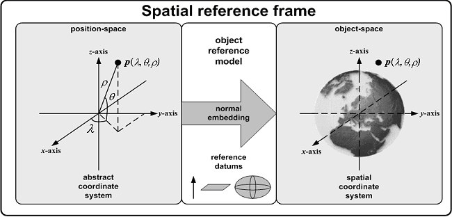
The relationships among some of these concepts are depicted in the following figure. An abstract coordinate system is based on the underlying Euclidean structure of position-space. The reference datums that comprise the object reference model determine how position-space relates to object-space. That relationship is mathematically expressed by a normal embedding. A spatial reference frame combines the abstract coordinate system with the object reference model to specify a spatial coordinate system. This allows positions to be expressed relative to a spatial object of interest, such as the Earth.
A spatial coordinate system is a means of associating a unique coordinate with a point in object-space. It is defined by binding an abstract Coordinate System (CS) to a normal embedding. A spatial reference frame is a specification of a spatial coordinate system for a region of object-space. It is formed by the binding of an abstract coordinate system to the normal embedding specified by an Object Reference Model (ORM) for that object. A full specification specifies the CS and the ORM and includes values for CS parameters, if any, and a specification of the region of object-space. Some or all CS parameters may be bound by ORM parameters. In particular, a CS based on an oblate ellipsoid (or sphere) must match the parameters of the oblate ellipsoid (or sphere) Rerefence Datum of the ORM.
A spatial reference frame template is an abstraction of a collection of spatial reference frames that share the same abstract coordinate system, coordinate system parameter binding rules, and similar ORMs that model the same spatial object type. Spatial reference frames may be organized into specified sets so as to form an atlas for a large region of space. The SRM specifies a collection of spatial reference frame templates, realizations of those templates, and sets of those realizations.
The SRM defines the following SRF Templates (SRFT):
The SRM defines the following SRF Sets and their intrinsic SRF template types:
The SRM defines the following Standard SRFs and their intrinsic SRF template types:
A reference datum is a geometric primitive in position-space. Reference datums are points or directed curves in 2D position-space or points, directed curves or oriented surfaces in 3D position-space.
A reference datum is bound when the reference datum in position-space is identified with a corresponding constructed entity (i.e., a measured or conceptual geometric aspect of a spatial object) in object-space. The term "corresponding" in this context means that each position-space reference datum is bound to a constructed geometric entity of the same geometric object type. That is, position-space points are bound to object-space points, position-space lines to object-space lines, position-space curves to object-space curves, position-space planes to object-space planes, and position-space surfaces to object-space surfaces.
A set of bound Reference Datums can be selected so as to be compatible with only one normal embedding. In this way, a set of bound RDs with properly constrained relationships can specify a unique normal embedding. Such a constrained set of bound RDs is called an object reference model.
An object reference model (ORM) for a spatial object is a set of bound RDs for which there exists exactly one normal embedding that is compatible with each bound RD in the set. In the 3D case, this unique embedding shall also be right-handed.
An ORM is object-fixed if each of its RD bindings are object-fixed; otherwise it is called object-dynamic. The object-fixed definition assumes that the object itself is not changing in time by an amount significant for the accuracy and time scale of an application. The normal embedding determined by an ORM is, correspondingly, either an object-fixed embedding or an object-dynamic embedding.
Examples of ORMs are: World Geodesic System 1984 (WGS 1894), and COAMPS, and Heliocentric Aries Ecliptic.
For 3D ORMs, a reference transformation shall be specified by the seven parameters of the corresponding seven-parameter embedding specification. For 2D ORMs, a reference transformation shall be specified by the four parameters of the corresponding four-parameter embedding specification.
For a list of supported reference tranformations for each ORM see the ORM-RT Relationship Table. Notice that the leading part of each RT name is the name of the ORM with which it is associated.
An abstract coordinate system is a means of identifying positions in position-space by coordinate n-tuples. An abstract coordinate system is completely defined in terms of the mathematical structure of position-space. In the SRM, the term "coordinate system" is defined to mean "abstract coordinate system".
A temporal coordinate system is defined as a means of identifying events in the time continuum by coordinate 1-tuples using an abstract coordinate system of coordinate system type 1D. A spatial coordinate system is defined as an abstract coordinate system suitably combined with a normal embedding as a means of identifying points in object-space by coordinate n-tuples.
A coordinate is an element of the coordinate system domain. In particular, if the domain is a subset of 3D Euclidean space (R3), each coordinate is called a 3D coordinate. If the domain is a subset of 2D Euclidean space (R2), each coordinate is called a 2D coordinate. Surface coordinates are defined as the projection of the 3D coordinate onto the surface of a RD.
Examples of coordinates are: Celestiocentric 3D coordinate, Local Space Rectangular 2D coordinate, and Transverse Mercator surface coordinate.
Note that this SRM release only supports the EGM_96 Geoid and WGS_84 Ellipsoid DSS codes for the Vertical Separation Offset calculation. See the Release Notes for additional information.
These are conversions that have an algorithm implemented between the source SRF and the target SRF.For instance, the coordinate conversion from a Celestiodetic SRF to a Celestiocentric SRF is a direct conversion.This type of conversion does not involve intermediate SRFs for its computation and thus they are most efficient.
These conversions are chains of direct conversions, converting first from the source SRF to intermediate SRFs, then to the target SRF. Consequently, these conversions typically take more time to be executed.For instance, the coordinate conversion from a Transverse Mercator SRF to a Celestiocentric SRF is an indirect conversion going through an intermediary conversion to Celestiodetic SRF.
Reflexive conversions are the cases where the source and the target SRFs are of the same class. The trivial case of this type of conversion is when the source and the target SRFs have the exact same parameter values.In that case, the identity transformation is applied to the source coordinate.Another example, when converting from a CD SRF to another CD SRF with a different ORM/RT pair, a datum shift is performed by converting the coordinate from the source CD SRF to an intermediate CC SRF, apply the datum shift, and then to the target CD SRF.
The type of conversion applied to the coordinates is transparent to the users. The users can invoke the SRM_changeCoordinateSRF() method, regardless of whether the conversion is direct, indirect, or reflexive. The API will perform the conversion in a most efficient way.If a conversion is not supported between the two given SRFs, then the call to SRM_changeCoordinateSRF() will raise an exception.
The chart below is provided as a reference to indicate which coordinate conversions are supported in SRM Version 4.2.0.Empty cells indicate conversions not supported in 4.2.0.
| LSA | CC | CD | CM | EC | EI | HAEC | HEEC | HEEQ | LCC | LCE_3D | LSR_2D | LSR_3 | LTSAS | LTSC | LTSE | M | OM | PD | LSP | PS | SEC | SEQ | SME | SMD | TM | |
|---|---|---|---|---|---|---|---|---|---|---|---|---|---|---|---|---|---|---|---|---|---|---|---|---|---|---|
| LSA | R | D | I | |||||||||||||||||||||||
| CC | R | D | D | I | D | D | D | D | I | D | I | I | D | I | I | I | I | D | D | I | ||||||
| CD | D | R | I | D | I | I | I | I | D | I | I | I | I | D | D | D | D | I | I | D | ||||||
| CM | D | I | R | I | I | I | I | I | I | I | I | I | I | I | I | I | I | I | I | I | ||||||
| EC | I | D | I | R | I | I | I | I | I | I | I | I | I | I | I | I | I | I | I | I | ||||||
| EI | D | I | I | I | R | I | I | I | I | I | I | I | I | I | I | I | I | I | I | I | ||||||
| HAEC | D | I | I | I | I | R | I | I | I | I | I | I | I | I | I | I | I | I | I | I | ||||||
| HEEC | D | I | I | I | I | I | R | I | I | I | I | I | I | I | I | I | I | I | I | I | ||||||
| HEEQ | D | I | I | I | I | I | I | R | I | I | I | I | I | I | I | I | I | I | I | I | ||||||
| LCC | I | D | I | I | I | I | I | I | R | I | I | I | I | I | I | I | . | I | I | I | I | |||||
| LCE_3D | D | I | I | I | I | I | I | I | I | R | I | I | I | I | I | I | I | I | I | I | ||||||
| LSR_2D | D | R | D | |||||||||||||||||||||||
| LSR_3D | R | |||||||||||||||||||||||||
| LTSAS | I | I | I | I | I. | I | I | I | I | I | . | . | R | I | D | I | I | I | I | I | I | I | ||||
| LTSC | I | I | I | I | .I | I | I | I | I | I | . | . | I | R | D | I | I | I | . | I | .I | I | I | |||
| LTSE | D | I | I | I | . I | I | I | I | I | I | . | . | D | D | R | I | I | I | . | I | I | I | I | |||
| M | I | D | I | I | I | I | I | I | I | I | I | I | I | R | I | I | I | I | I | I | ||||||
| OM | . | I | D | I | I | . I | I | I | I | I | I | . | . | I | I | I | I | R | I | . | I | I | I | I | ||
| PD | I | D | I | I | I | I | I | I | I | I | I | I | I | I | I | R | I | I | I | I | ||||||
| LSP | I | D | R | |||||||||||||||||||||||
| PS | . | I | D | I | I | . I | I | I | I | I | I | . | . | I | I | I | I | I | I | . | R | .I | I . | I | ||
| SEC | D | I | I | I | I | I | I | I | I | I | I | I | I | I | I | I | I | R | I | I | ||||||
| SEQ | D | I | I | I | I | I | I | I | I | I | I | I | I | I | I | I | I | I | R | I | ||||||
| SME | R | |||||||||||||||||||||||||
| SMD | R | |||||||||||||||||||||||||
| TM | I | D | I | I | I | I | I | I | I | I | I | I | I | I | I | I | I | I | I | R |
The details on how to instantiate SRFs, instantiate coordinates and convert coordinates are as follows:
There are three ways to instantiate SRFs depending whether they are instances of SRF Templates, SRF Sets, or standard SRFs. Once an SRF is instantiated, its parameter values cannot be changed:
There are 26 SRF Template classes in SRM. These include SRF_Celestiodetic, SRF_Celestiocentric, SRF_LocalSpaceRectangular3D, and Transverse Mercator. Use their class constructors to instantiate these types of SRFs. For example, to instantiate a Celestiodetic SRF using the WGS 1984 ORM with the Identity RT transformation:
     SRF_Celestiodetic my_cd_srf = new SRF_Celestiodetic
                                       ( SRM_ORM_Code.ORM_WGS_1984,
                                         SRM_RT_Code.RT_WGS_1984_IDENTITY );
There are 7 SRF Sets currently defined in SRM. This includes Universal Transverse Mercator (UTM), Geo Tile Reference System (GTRS), Global Coordinate System (GCS), and Universal Polar Stereographic (UPS). Each of these SRF Sets are composed of a well-defined set of members. For example, UTM is composed of 120 members (zones) while GTRS GCS has 59,896 members (cells). Instances of these SRF Set members can be instantiated by invoking the static createSRFSetMember method in the BaseSRF class. For example, to create an instance of UTM zone 12 in the Northern hemisphere using the WGS 1984 ORM with the Identity reference tranformation:
SRF_TransverseMercator my_utm12_srf = BaseSRF.createSRFSetMember
                                          ( SRM_SRFS_Code.UNIVERSAL_TRANSVERSE_MERCATOR,
                                            SRM_SRFSM_UTM_Code.SRFSMUTM_ZONE_12_NORTHERN_HEMISPHERE,
                                            SRM_ORM_Code.ORM_WGS_1984,
                                            SRM_RT_Code.RT_WGS_1984_IDENTITY );
The SRF template type for the Universal Transverse Mercator SRF is intrinsically
Transverse Mercator. In other words, the instantiated UTM SRF is actually an instance
of the Transverse Mercator SRF Template, and therefore, supports all the methods
defined for that SRF Template. Likewise, for example, a GTRS GCS SRF is intrinsically
an instance of the Local Tangent Space Euclidean SRF Template.
There are 14 Standard SRFs currently defined in SRM. These include British National Grid Airy (BNG), Irish Grid, and the Maryland State Plane Coordinate System (SPCS). Instances of these Standard SRFs can be instantiated by invoking the static createStandardSRF() method in the BaseSRF class using the proper SRF code. For example, to instantiate an instance of BNG with the OSGB 1936 England reference tranformance:
SRF_TransverseMercator my_bng_stf = BaseSRF.createStandardSRF( SRM_SRF_Code.SRF_BRITISH_NATIONAL_GRID_AIRY,
                                                               SRM_RT_Code.RT_OSGB_1936_ENGLAND);
The SRF template type for the British National Grid SRF is intrinsically
Transverse Mercator. In other words, the instantiated BNG SRF is actually an instance
of the Transverse Mercator SRF Template, and therefore, supports all the methods
defined for that SRF Template. Likewise, for example, a Maryland SPCS SRF is
intrinsically an instance of the Lambert Conformal Conic SRF Template.
The ORM parameter is pre-defined for each standard SRF. Users can only specify the reference transformation parameter that are applicable to that particular ORM. The pre-specified ORMs for the standard SRFs are as follows:
Each SRF Template has its specific coordinates defined. The coordinates are only valid when associated with a specific SRF. Depending on the SRF instantiated, 2D, 3D or surface coordinates can be instantiated from it. There are mainly two way to instantiate coordinates:
A SRF instance can instantiate a coordinate associated with the SRF using the createCoordinateXX() method, where "XX" can be "2D", "3D", and "Surf" depending on the STF. For example, to instantiate a 3D coordinate for a Celestiodetic SRF:
Coord3D_Celestiodetic my_cd_3d_coord
                   = (Coord3D_Celestiodetic)(my_cd_srf.createCoordinate3D( 0.8987, 0.5645, 1000.0 ));
Another example to instantiate a UTM surface coordinate for a UTM SRF:
CoordSurf_TransverseMercator my_utm_surf_coord
                   = (CoordSurf_TransverseMercator)
                                  (my_utm12_srf.createSurfaceCoordinate( 500.0, 320.0 ));
Notice that the instantiate UTM SRF is intrinsically
a TM SRF, and therefore, supports the createCoordinate3D method defined in the
TM SRF Template class. Consequently, the surface coordinate instantiated by the UTM SRF
is of CoordSurf_TransverseMercator class.
Each coordinate class takes in its constructor a SRF parameters to which the coordinate is associated. For example, to instantiate a 3D coordinate for a Celestiodetic SRF:
Coord3D_Celestiodetic my_cd_3d_coord
                   = new Coord3D_Celestiodetic( my_cd_srf, 0.17865, 0.01234, 1000.0 );
To instantiate a UTM surface coordinate for a UTM SRF:
CoordSurf_TransverseMercator my_utm_surf_coord
                   = new CoordSurf_TransverseMercator( my_utm12_srf, 500.0, 530.0 );
Having instantiated the source and target SRFs and coordinates, invoke the changeCoordinateSRF() method of the target SRF to calculate the target coordinate and the Valid Region. For example, to convert a Celestiodetic 3D coordinate to a Transverse Mercator SRF:
Coord3D_TransverseMercator my_utm12_3d_coord( my_utm12_srf );
validRegion = my_utm12_srf.changeCoordinateSRF( my_cd_3d_coord, my_utm12_3d_coord );
In this example, the 3D Celestiodetic coordinate is converted to a UTM SRF. The validRegion indicates where the resulting UTM coordinate is within the valid, extended or defined regions.
A Direction object can be instantiated using the createDirection() method in any subclass of BaseSRF_3D. For example, to instantiate a Direction using a Celestiodetic 3D coordinate "cd_ref_location" associated with and a direction vector (1.0, 2.0, 3.0):
Direction my_cd_dir = my_cd_srf.createDirection( my_cd_ref_location, {1.0, 2.0, 3.0});
The Celectiodetic SRF "cd_srf" must be the same one used to instantiate both the
reference location "cd_ref_location" and the direction object "cd_dir".
Having instantiated the source and target SRFs and Directions, invoke the changeDirectionSRF() method of the target SRF to calculate the target direction and the Valid Region. For example, to convert the Celestiodetic direction to a Transverse Mercator SRF "tm_srf":
validRegion = my_tm_srf.changeDirectionSRF( my_cd_dir, my_tm_dir);In converting a Direction, both its reference location and the vector are converted to the target SRF. The valid region is associated with the resulting reference location.
SRF_Celestiodetic cd_srf = new SRF_Celestiodetic
                                   ( SRM_ORM_Code.ORM_WGS_1984,
                                     SRM_RT_Code.RT_WGS_1984_IDENTITY );
Coord3D_Celestiodetic cd_3d_coord
                   = new Coord3D_Celestiodetic( cd_srf, 0.8987, 0.5645, 1000.0 );
SRF_Celestiocentric cc_srf = new SRF_Celestiocentric
                                       ( SRM_ORM_Code.ORM_WGS_1984,
                                         SRM_RT_Code.RT_WGS_1984_IDENTITY );
Coord3D_Celestiocentric cc_3d_coord
                   = new Coord3D_Celestiocentric( cc_srf, 4517590.0, 0.0, 4487350.0 );
OrientationTaitBryanAngles ori_tb = new OrientationTaitBryanAngles();
cc_srf.computeSRFOrientation( cd_3d_coord,
		              cc_3d_coord,
		              ori_tb );
import SRM.*;

public class CdToCcConv
{
    public static void main (String args[])
    {
	System.out.println( "*** Sample program using SRM Java API to convert a 3D coordinate" );
	System.out.println( "*** from a Celestiodetic SRF to a Celestiocentric SRF." );

	// Declare reference variables for the CD and CC SRFs
	SRF_Celestiodetic CdSrf = null;
	SRF_Celestiodetic CdSrf1 = null;
	SRF_Celestiocentric CcSrf = null;

	try {

	    // Create a Celestiodetic SRF with WGS 1984
	    CdSrf = new SRF_Celestiodetic(SRM_ORM_Code.ORM_WGS_1984,
	    				  SRM_RT_Code.RT_WGS_1984_IDENTITY);

	    // Create a Celesticentric SRF with WGS 1984
	    CcSrf = new SRF_Celestiocentric(SRM_ORM_Code.ORM_WGS_1984,
					    SRM_RT_Code.RT_WGS_1984_IDENTITY);

	    // Create a 3D Celestiodetic coordinate with
	    // longitude           => 10.0 degrees (note: this input parameter is converted to radians)
	    // latitude            => 20.0 degrees (note: this input parameter is converted to radians)
	    // ellipsopidal height => 100.0 meters
	    Coord3D_Celestiodetic CdCoord =
		(Coord3D_Celestiodetic)CdSrf.createCoordinate3D(Math.toRadians(10.0),
								Math.toRadians(20.0),
								100.0);

	    // Instantiate a 3D Celestiocentric coordinate
	    // This is an alternative method for instantiate a 3D coordinate
	    Coord3D_Celestiocentric CcCoord = new Coord3D_Celestiocentric( CcSrf );

	    // print out the SRF parameter calues and the coordinate component values
	    System.out.println("CdSrf parameter =>  \n" + CdSrf);
	    System.out.println("CcSrf parameter =>  \n" + CcSrf);
	    System.out.println("CdCoord components (source) => \n" + CdCoord);

	    // convert the 3D Celestiodetic coordinate to 3D Celestiocentric coordinate
	    SRM_Coordinate_Valid_Region_Code valRegion =
		CcSrf.changeCoordinateSRF( CdCoord, CcCoord );

	    // print out the values of the resulting 3D Celestiocentric coordinate
	    System.out.println("CcCoord components (destination) => \n" + CcCoord + " is " + valRegion );

	}
	catch (SrmException ex)
        {
	    // catch SrmException and print out the error code and text.
	    System.out.println("Exception caught=> " + ex.what() + ", " + ex);
	}
    }
}
Executing the sample code would result the following output:
*** Sample program using SRM Java API to convert a 3D coordinate
*** from a Celestiodetic SRF to a Celestiocentric SRF.
CdSrf parameter =>
orm: ORM_WGS_1984
rt: RT_WGS_1984_IDENTITY
CcSrf parameter =>
orm: ORM_WGS_1984
rt: RT_WGS_1984_IDENTITY
CdCoord components (source) =>
[ 0.17453292519943295, 0.3490658503988659, 100.0 ]
CcCoord components (destination) =>
[ 5904838.698311626, 1041182.3792437915, 2167730.9898430835 ] is VALID
Return to: Top
Copyright © 2010 SEDRIS™